
Prosthetic Hand
Ever since I got involved with 3D printers I was always fascinated by the possibilities of creating prosthetics with them- the growing affordability and availability of 3D printers, model repositories, and CAD software could allow for incredible access to tools and even limbs for people in need. There are currently some prosthetics available on 3DUniverse and Thingiverse that are often downloaded, but I found many of these designs to be lacking in durability.
This project will be the culmination of my passive research into prosthetics. This is also a great reprieve from both waiting for the department head at Georgia Tech to approve old courses as I transfer. It also helps to alleviate my stress as I wait for employers to hire me as I wade through the hell that is the post-COVID job market. I aim to make a sturdier and perhaps more expedient alternative for 3D printing this prosthetic using Solidworks but to also document the steps I have taken to design this project in case people would like to modify it.
You can find the files for the project here.
Update 01/06/2021: Wrist and Tension Parts
For this version of a prosthetic hand, I currently do not have the means to secure actual servos and electrode sensors to make a more mechanized prototype. That project would have been all the more unlikely due to the fact that I'm physically moving to Georgia Tech in five days, and by the time those components would arrive I would no longer have my usual tools to actually build the thing. So, for now, that plan is scrapped. Maybe for the future.
I had to keep things simple. I had some fishing line from leftover projects, and so I set to work on thinking of a passive mechanism. The basic design revolves around the inelastic string tethered to a fixed point and a fingertip, and the assumption that the amputee still has their palm. As the palm swivels backward, the strings become taut, which then pull at the fingertip to curl it. Many current models use that simple design, so it's tried and tested, but it can be improved.
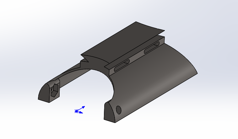
The first thing I set out to design was the wrist. I figured it would be a nice baseline to build off of, as I could scale the proportionality of my parts from that. I started off with a half-ellipse, and then added some mass to the top half for the tensioner. I added holes for the palm part for M4 bolts, with some care to add some meat to prevent cracks from forming over time. I also added hexagonal cutouts for the nuts so they'd be flush and not irritate the skin of the user.
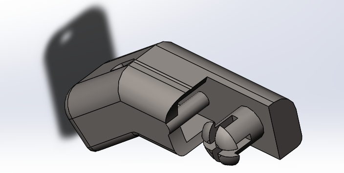
You need a tensioner in order to properly tune the wires for proper actuation of the fingers. As for securing it, I wanted to make sure it wouldn't budge if banged against. To ensure it didn't wobble or pull apart, I incorporated a dovetail design. The tensioner itself also has holes for M3 screws to properly secure it to the wrist. The tensioner also has small arms that face towards the fingers to which the lines would be tied, of which both the main unit and the arm would be connected by an M2.5 screw. These arms were separate from the main tensioner assembly so that if one of the lines was too slack you could tighten its appropriate screw to make it tauter. The choices of M2.5 and M3 bolts were due to me having them handy.
The M2.5 bolts are quite close to each other, but still compact enough without having any interference. The M3 bolts, however, were a different story. Initially, they were way too close to the heads of the M2.5 bolts. I had to extend the base of the tensioner by 0.25" such that the heads of the M3 bolts had enough clearance. I also added some slots under the dovetail of the wrist for velcro straps to fit.
Design - Ryan Aday


To prepare these parts for FEA, I needed to convert the material to PLA. I intend to print with PLA (polylactic acid) since it produces more detailed prints, is the filament of choice for most people, and probably the most accessible at Georgia Tech Since Solidworks' plastic materials have never been updated since the age of the dinosaur, I had to figure out the properties. Here are the sources I used below to establish those properties:
Advanced Drug Delivery Reviews Paper (wonder why they'd use PLA to transport a drug, to be honest)
Due to my inability to find the actual custom file I wrote for PLA, here is a photo of most of the attributes below. Its damping ratio is 2.2.

Update 01/07/2021: Palm Part
Today's been a bit hectic, so I didn't have the chance to get started on the next phase of the project as I would have liked. Regardless, I did mostly finish up on the palm. I'm thinking of keeping viewers more informed of my design projects, especially since I came across steep bottlenecks due to issues with Solidworks itself. Don't get me wrong, Solidworks is by no means bad CAD software, but sometimes interacting with its operations can really grind your gears if you can't find the problems.
Designing the palm is more of an art than it is a clinical design experience. Sure, you could keep the overall design of the hand really blocky, but I wanted to make it look natural while employing a more structured approach to making it. If I wanted to sculpt a hand I would have tried doing so in Blender. However, this project is designed to be easily editable, so those with poor sculpting skills like me would still end up with a really nice and tuneable product.
I constructed the palm based on the assembly, which you can do by creating a new part within it. It's easier than having to design parts independently of each other without context. Every sculpt starts off as a block, so I began from there by extruding a rectangle from the wrist plane that was a little smaller than the space I provided for the wrist for the sake of clearance. I wanted to add a bit of curvature to the left edge of the hand (since the prosthetic is designed around the left hand, but can be mirrored for the other) due to more surface area and being how human hands actually are. I used a conic curve to generate that and defined it, extruding it until it met the rest of the block.
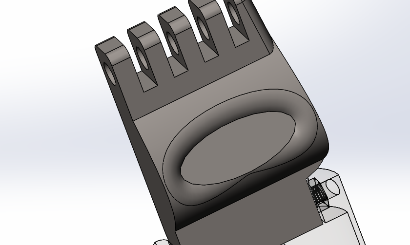
I also wanted to create a natural recess in the base of the palm, which would help with both gripping and holding items, also just like human hands. It took a bit of experimenting, but what I ended up doing was using a spline to create a gentle rise near the bottom of the palm, in which I took measurements similar to my own hand. I then created an angled plane that intersected with that rise, and I cut an ellipse into it, though not very deeply. I then filleted the edges to make a more gentle curvature. I think it looks great!
The hand also needs space for a joint for the fingers. I cut into the top of the palm four slots, one for each of the fingers except for the thumb. I added ample space for thicker joint structures for added durability as well as for room to provide for future clearance. I also added a nice fillet to make the overall shape of the palm less blocky. Remember, filleting is fine since we're 3D printing the thing!
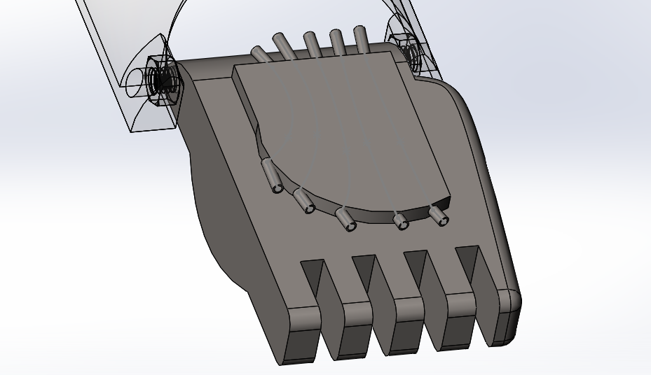
Trouble began when I began making the string guide. Making the overall body of the spline wasn't too bad; I extruded a bit away from the main body of the palm and used a spline to make its general shape. However, Solidworks is a bit crummy due to the fact that you can't simply make a weird curved hole by means of a spline. I needed to make these curved holes in order to properly organize the string within the guide.
It took me a while but I finally figured that one way to make these holes was to sketch the spline with lines trailing their ends. Making these lines into weldment profiles first (since using splines is forbidden by the Structural Member feature gods) needs to be done. You can then use the inner curve of these new bodies to then use a loft cut, but you need to select the centerline as the spline to properly guide the hole through the correct path. Make sure that these inner curves properly align by making sure they are angled the same way.
It also helps to keep the palm transparent as you draw the splines to make sure the holes don't intersect and aren't misshapen.
Making the weldment profile itself is relatively simple. Make a new part and draw the outline of the profile. After the sketch is complete, make sure to right-click it and click on "Add to Library". This allows for the profile to be created without instantiating issues. Not doing so will prevent it from being properly recognized. I made a circular profile with 0.05" as the ID and 0.06" as the OD.

When saving the profile, make sure it ends in *.sldlfp. That indicates that it's a template file. Make sure it is nested within a folder of a subfolder of the main source of the profiles (I.e. weldment profiles> User>Hand> <Your_file_here>). It's a Solidworks thing in which the software needs to hunt within the file structure like that, it's poorly written.
If you've got admin access issues like me where you're unable to change the provided root folder given to you like Solidworks despite being an admin (classic Solidworks) there's a way to introduce a new root folder. Go to options and add the address from File Locations under the tab "Weldment Profiles". If you don't know the PATH you can copy-paste it there.

Investigating the current design I widened the main tensioner's bolt holes to 0.09" from 0.07" since the bolts shouldn't be hard to tighten; they should primarily pull at the arms, and the less effort the user has to exert to tune the tension the better.
Due to it being about 4:20 by the time I write this (hey) I figure I should call it quits for tonight. I plan to tackle several things tomorrow.
-
I added a pin hole for the finger joints, but I still need to design the pin for them.
-
Work on fingers should get started tomorrow. I'm thinking off adding texture to them to make them more grippy.
-
I noticed that the tensioner arms are thinner than the bolts that are currently in the assembly. I need to either change the bolts or make these arms wider; probably the former since that requires the least change.
-
There is currently a through-hole at the wrist for the joints. Should I keep it a through-hole for whatever size bolts to be used, or make it more constrained to keep structural integrity?
-
Work on thumb joint? Still needs to be added to the palm.
Update 01/08/2021: Progress Update
Due to having spent the entirety of my waking moment running around the city looking for COVID testing sites for GT and finally finding one that performs rapid testing without the need for a doctor's note or prescription, I'm exhausted. It's unbelievable why after all this time the majority of these centers require something like that, especially since if I'd need a doctor's note to be tested to COVID I'd probably have it anyways. I'm also taking this opportunity as a means to fix my sleep schedule since I've noticed the habit of updating this website during the wee hours of the night. Sorry for no proper updates today, but I plan to continue as normal tomorrow, and hopefully update this website much earlier than at 4 AM.
Update 01/10/2021: Palm Redesign and Knuckles


Pretty hectic today since I'm about to leave for Georgia Tech by 6 PM tomorrow evening, but managed to get some work done. Today was more trial-errory, and I realized I had made a massive mistake since first making the palm.
When initially working on the palm I had forgotten to remember that the overall dimension had been based on the width of the wrist. Therefore, the knuckle distances were all wack- extremely close to each other- and I'm surprised I didn't catch that earlier.
I, therefore, had to redesign the palm. Keeping the same design language, I used splines to make natural curvatures. Lengthening the width also caused a bunch of errors with routing the thread holes. Solidworks has really crappy routing when it comes to making lofted holes, so you have to be very particular with the routes. Adding new spline points helped, but it was still very much a trial and error timesink to figure out good routes so as to not unintentionally create holes with bottlenecks.
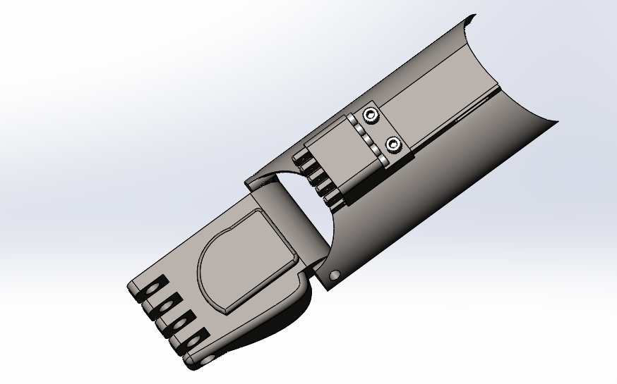
I also added slots to the palm for the use of Velcro to be used to secure the amputee's palm to the prosthetic. The slots are placed at points such that they avoid the wire routing while allowing pretty secure mounting. To make the palm more comfortable I cut out way more space for it to rest in, and also made a little cut out for the wrist. I also noticed that the wrist bolt holes for the palm really didn't have a lot of material, so I added a small bump to prevent fatigue wear and tear.
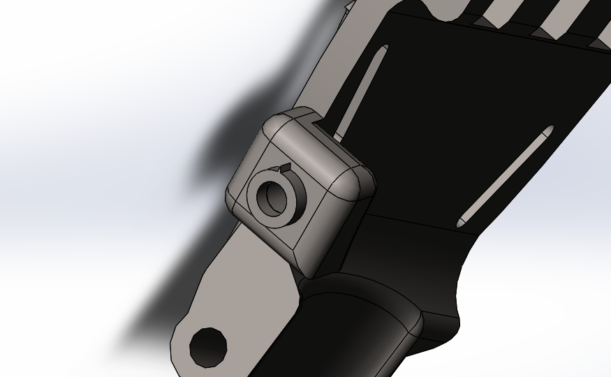
When working on the knuckles I also had to do a bit of guesswork to determine tolerances. I had 0.02" gaps between the palm and the knuckles,, which should be plenty for somewhat poorly tuned printers. I made the length about as long as mine at about 1", though you can easily extend them if you prefer. I incorporated a hexagonal grip pattern too. If someone were to print the knuckles in TPU they'd be even grippier. I plan to do something similar for the actual digits.
For securing the knuckles I came up with a long main pin idea that did not require the need for additional bolts. There was enough space left on the palm that I could cut out space for a key shaft, and I designed the pin with a key that should be easy to print. The end of the shaft also has slots to be turned with a Phillips screwdriver, and the face should be flush with the surface of the palm for a clean look.
To address more errors from Wednesday, I checked the bolts on the tensioner that I thought were too big. Turns out they were. I had referenced the wrong bolt that I had measured when inserting them, and the M2.5x10 bolts have been replaced with the proper M2x10 bolts. I've also added some divots for the M4 bolts at the wrist so they sit more flush with it, though I've kept the hole hollow if users decide to use longer bolts than what's on the model.
I'm not sure if I'll be able to work on this tomorrow due to my driving to GT, but here's some work for tomorrow and later:
-
The thumb mount on the palm and the actual digits need to be designed. Look into grips that could be more effective with TPU.
-
Further design optimization for the palm? Probably could make the slots better, some clearances larger, and some trouble points less troubled.
-
FEA on some parts to check how strong they'd be.
Update 01/12/2021: Palm Redesign and Knuckles


Sorry for the short hiatus, but I've been getting acclimated to Georgia Tech and its lack of open food courts. It's been a rough day wading through issues with applying for courses (typical college experience). Working on this helped with the waiting for no conclusive response. Brianna Leung is also now involved with the project, which will help her mature her keen interest in bioengineering.
I mostly worked on the fingers today. I originally had trouble with figuring out how to join the knuckle and tip parts due to clearance issues with the joints next to each other. To maximize the clearance I went about forgoing any screws since their heads would be relatively wide even if they were M2s, and instead went with designing compliant pins that could be 3D printed easily. Despite these being 3D printed I made sure the forks would be thick enough to still be intact after insertion, with enough space to grab onto excess material.
I made sure to add 0.075" of space and made their OD's 0.06" wider than that of the pivot holes, but soon realized that even this solution would not provide desired levels of clearance. I also tried thinning the knuckles, but that didn't help too much.

I then came up with the plan of using the same method from the compliant pins but extending them to the rest of the fingertip as one part. I redid half of the pin and sculpted the general shape of the finger via rectangular extrusions and fillets. I hollowed a small section near the pivot and added a slot and catch to allow for the string to pass through that shell, loop around the front, and then be tied to that catch. I designed it so it would be reasonable to do with one hand.
Misediting and hours of redoing my work later, I was able to make editing the sizes of the fingertips pretty easy by adjusting one dimension. The section between the actual tip and the joint (let's call it the base) has a length of 0.7", 0.8", and 1", modeled after my own hand for the meantime.
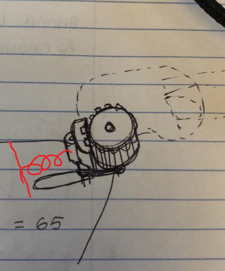
Brianna and I also came up with two ideas for a thumb joint. The thumb join needed to be quick to adjust and articulate. I wanted the thumb joint to be as small and comfortable as possible while using the least amount of material possible, so I came up with an idea of "frictional gears"- essentially two miter-like gears that have their teeth intersecting each other such that they hold their relative position unless forced to turn. The main issue with that system would be the gradual wear and tear. Within a year, the gears would need to be replaced if they were made with PETG, and less if it was PLA. The mechanism would have to be quickly interchangeable, so a screw through one of them could work to hold it in place.

Brianna proposed something more akin to a pawl and ratchet mechanism, which would have a pawl physically stopping the gear from turning. The pawl would move along and be bolted to a fixed point, so that if the user needed to adjust the thumb they'd need to unscrew that bolt first. This was a more robust design, but the mechanism seemed bulky since it would be mounted close to the palm, which would interfere with the amount of space the user had to be able to grab with. The hole that the screw would thread would wear over time too.
We came up with an improvement on the pawl mechanism, in that instead of a fixed point pawl we could use something like a pen spring to keep pressure on it. That way we would easily adjust the thumb by sliding the pawl back. The pawl would still need to be slotted in order to make sure that the movement stayed consistent. Work would also need to be done with the size of it, but so far it's a nice compromise between that, durabily, and ease of use. We'll think about it more in the future.
For next time:
-
I realize there might be a more clever way to incorporate joints. Perhaps I can later design a print-in-place ball joint system, since due to the way the strings are inelastic and the prosthetic relies on tension would be fine, and would allow for greater articulation.
-
Knuckles need to be thickened from last time, I just got tired and wanted to stop for today.
-
More research and planning to be done for the thumb pivot.
Update 01/16/2021: First Prototype Completed!


Apologies again for the 4-day hiatus. After a hectic move-in, scramble for course selections, and worrying my sleep off on whether a professor would give me an advanced standing exam, I've now finished the hand.
Like previously mentioned, I wanted to widen the knuckles again as I thought they seemed too skinny and wanted more surface area for the user. I reverted my cuts to it.
As for the thumb mechanism, it might be nice to revisit older ideas, but for this iteration I wanted the easiest/least time-consuming method possible to mount a thumb that could be oriented. I went with the "friction gear" plan of having a master and slave gear, with the master having teeth being slightly shorter than the gearing of the slave so as to allow for smoother turning. Wear might be a problem, but the user can always print a new thumb joint when that happens.
I also wanted to recycle the mounts I used for the main fingers in case the user wanted to hot-swap a finger for a more comfortable/useable version. I made the cut at a 35 degree angle, which I felt should be nice enough for a more natural grip. For now, the thumb finger point is a mirrored middle-sized finger (like it is with my own hand). I had to make the part an assembly since mirrored parts save like that in Solidworks.
The thumb mount and palm pivot point mount using a M3x8-16 screw. I made a small divot in the palm to accommodate the head of the screw so it wouldn't dig into anyone's hands.
I planned to have parts printed, but the workspaces at Georgia Tech are all closed. I'd need to figure out a means to manufacture this elsewhere.
For printing, this should be fine for most FDM printers. The printers should not have any stringing though, or as little stringing as possible, 0.4 nozzles should work okay. All parts should be oriented with the flat face to the bed, use your best judgment. I use a glass bed for my prints on a Creality Ender-3, but realistically it should be fine for whatever you use.
PLA/TPU temps should be 215 degrees C with a bed temp of 60 degrees C. I'd use 90 shore hardness or higher though if you plan to print with TPU though. PETG should be similar for 240 degrees C with a bed temp of 70-80.
For later prototypes, if I choose to revisit this, I plan on looking into print-in-place ball and socket joints. It would allow for a greater range of natural motion due to the entire thing being based on tension, though durability is still a question. I'd also like to see if there's a better iteration of the thumb joint.
FEA and other studies to be performed eventually and posted here, but it's more secondary if anything.
Hope you found this as fun as I did, and please feel free to email me if you've got design tips/questions!